
Model Overview
The T-368/URT was a high-power shortwave radio transmitter widely used by the U.S. Army and Air Force during the Cold War. Entering service in the early 1950s and remaining in use through the mid-1970s, it replaced the World War II–era BC-610 as one of the U.S. military’s standard HF sets. Using vacuum tubes as power amplifying elements, the T-368 delivered formidable performance: in AM (amplitude-modulated) voice it could continuously output ~400 W carrier power, and in CW (continuous-wave telegraphy) its output exceeded 450 W. Its operating range covered roughly 1.5–20 MHz across the HF bands, enabling long-distance radio communications. Thanks to its rugged design, high output, and ability to run continuously, the T-368 became a core device at fixed and semi-fixed communications stations, serving both AM voice and CW Morse operations.
Notably, the T-368 was primarily employed on radio teletype (RTTY) networks. By connecting an external frequency-shift keyer, the transmitter could generate FSK signals to drive teleprinters for encrypted traffic. Its built-in AM voice capability ensured an immediate fallback to phone when needed. This versatility allowed the T-368 to handle strategic teletype, while also serving as a voice broadcast transmitter when required. In short, the T-368 represents a high-water mark of Cold War HF technology—delivering high power and duty cycle via vacuum tubes to meet the era’s military communications needs.
Context and Role
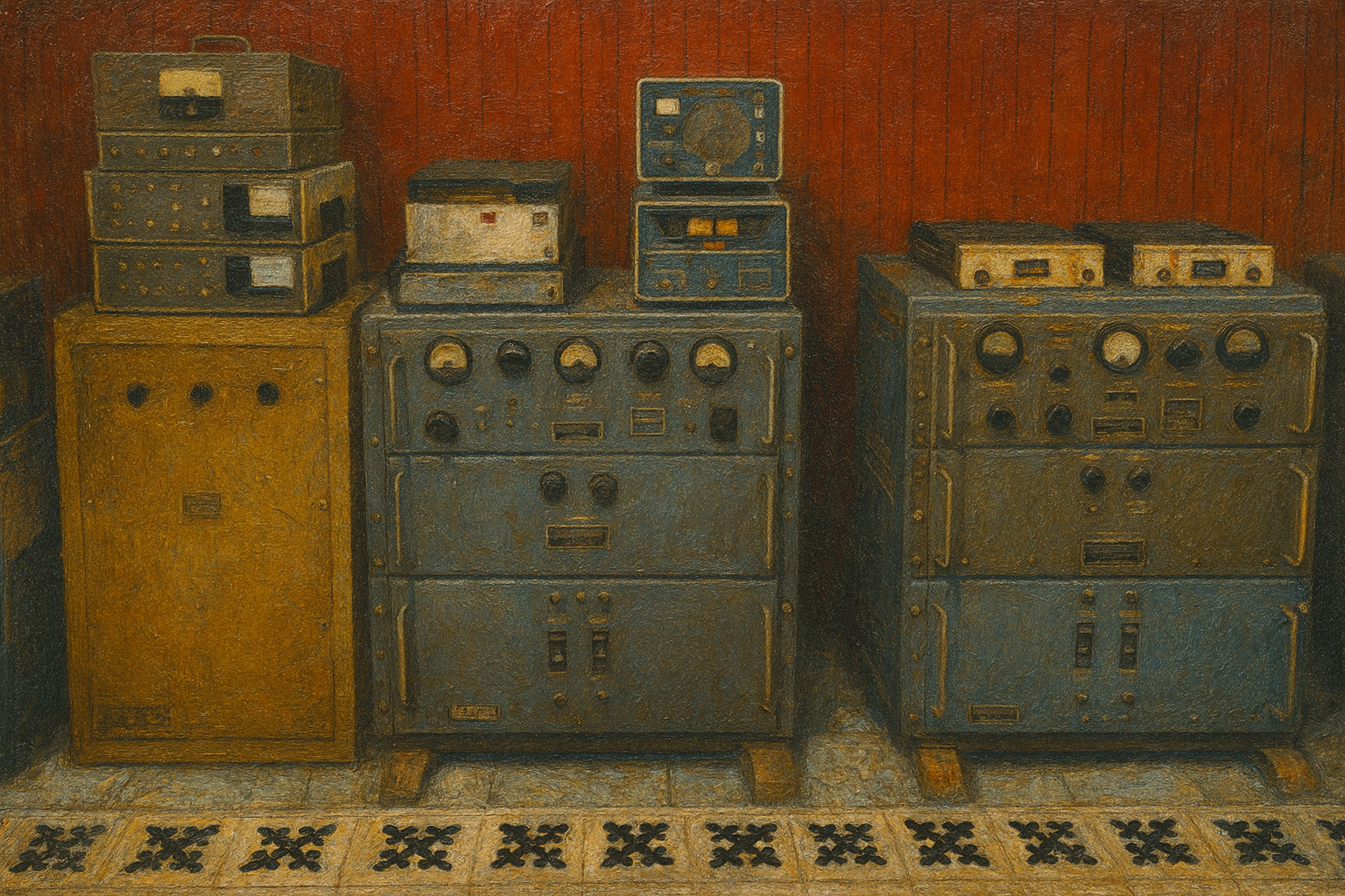
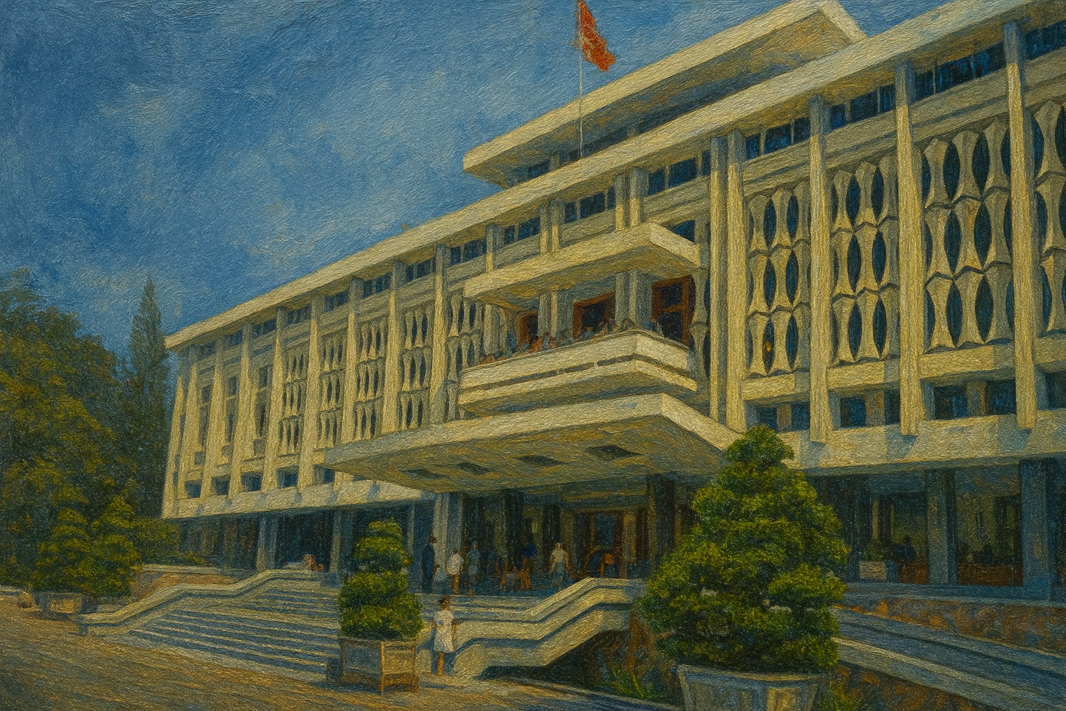
During the Vietnam War, multiple U.S.-made T-368 transmitters were installed in the communications hub in the basement of Saigon’s Independence Palace (today the Reunification Palace), supporting the South Vietnamese government’s high-level communications. As the presidential compound and military command center, the palace’s basement housed a dedicated communications room combining transmitters, receivers, cipher machines, and teleprinters into a strategic node. The T-368s served as the long-range outbound end, radiating voice or telegraph signals on HF to receivers across the country and abroad. Reports indicate the room held as many as five T-368 transmitters, numerous R-390 high-performance receivers, AN/FGC-25 RTTY terminals, TH-5 modems, and other peripherals—indicating the hub could handle simultaneous multi-frequency, multi-channel traffic with encryption, voice, and data capabilities.
In practice, the palace station relied on the T-368 + R-390 transmit/receive pairing, plus teleprinters and voice gear, to link the South Vietnamese government with U.S. forces and ARVN regional commands. For example, an encrypted message from U.S. headquarters might be received by an R-390 in the basement, decrypted and analyzed at the palace, then replied to via the T-368 over HF; or a frontline commander could send urgent reports through a tactical set to a nearby HF relay, which would forward them by T-368 to Saigon’s command center. Functionally, the palace’s basement communications room acted as the regime’s “neural hub,” ensuring that when landlines were cut or infeasible, orders and intelligence could still traverse vast distances by shortwave. Together, these T-368s and companion equipment formed a lifeline radio network that sustained links between the South Vietnamese government and U.S. advisory elements.

Architecture and Technical Parameters
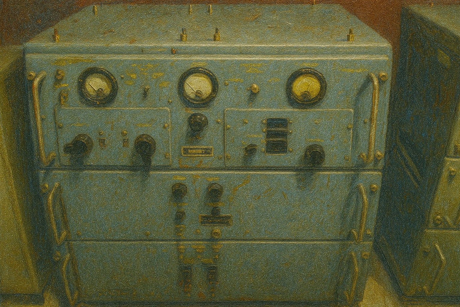
As a large, fixed-station HF transmitter, the T-368 was modular and physically substantial (total weight in the hundreds of kilograms). The main chassis was broadly organized into three decks: the top RF deck with the exciter/oscillator and power amplifier (PA); the middle modulator deck with speech amplification and high-level AM circuitry plus a pair of modulation tubes; and the bottom power/control deck with the high-voltage DC supply, rectifiers, and control relays. The PA used a large Eimac 4-400A as the final RF tube, while modulation employed two Eimac 4-125A tubes in push-pull to plate-modulate the PA. This all-tube lineup allowed sustained full-power operation under harsh conditions—but also meant significant heat generation (requiring forced-air cooling) and thousands of volts inside the cabinet, demanding careful operation and maintenance.
Typical Companion Equipment
To operate safely and match antennas, the T-368 was commonly paired with auxiliaries. One was the BC-939 antenna tuning unit, which matched the transmitter to various loads across 1.5–20 MHz, reducing VSWR and protecting the PA from reflected power. When no suitable antenna was available, a dummy load—a high-power resistive sink—could be attached to absorb RF output without radiating, enabling test and training. For power, the T-368 used 115 V AC mains (50–60 Hz), with a dedicated power module in the rack providing high-voltage DC and filaments. In field deployments—e.g., inside an AN/GRC-26D radio van/tent—PE-95 gasoline generator sets supplied the necessary power.
Front Panel and Tuning Procedure
The T-368’s front panel is densely populated with meters, switches, and controls in a functional layout. Close-ups show three large meters and multiple knobs for monitoring and adjustment. Typical controls include:
- Band Selector: Chooses the band segment for the operating frequency (e.g., 1.5–4, 4–8, 8–12 MHz), pre-tuning internal resonant circuits.
- Exciter Tuning: Tunes the exciter/driver resonance for maximum drive at the chosen frequency (using an external crystal or internal VFO as applicable).
- PA Plate Tuning: Adjusts the final tank circuit (variable capacitor) to resonate the PA anode circuit with the attached antenna/tuner. In CW tune, you slowly adjust while watching the plate current “dip” at resonance—starting at low power and finding the minimum current point.
- PA Loading: Sets the output coupling/loading to bring plate current up to rated values after resonance, achieving rated RF output without overloading. Operators typically “tune for dip” (Plate Tune) then “load” (increase current/output), iterating to reach manual-specified safe maxima.
- Service/Mode Selector: Selects AM (voice), CW (telegraph), or FSK (for RTTY). In FSK, an external O-5C/FR exciter module provides the shift; in AM, the internal modulator plate-modulates the PA; in CW, the modulator is bypassed and a key controls carrier on/off.
- Filament / Plate & Relay (Standby/Transmit): Separates filament warm-up from application of high voltage. Filaments are brought up first, then “Plate” HV is enabled; PTT or keying then switches the set from receive standby to transmit.
- Meter Switch: Selects which parameter the meters display—exciter current, PA plate current/voltage, etc.—so the operator can keep critical readings within limits during tune-up.
A standard tune-up goes as follows: select band and warm up; at reduced power, use Exciter Tuning and PA Plate Tuning to find resonance (plate current dip); then increase PA Loading to raise plate current and RF output to rated values; iterate tune/load adjustments to maximize output without exceeding limits. In AM, adjust modulator gain so voice peaks do not exceed 100% modulation to avoid distortion. Mode changes (e.g., CW↔AM) involve switching the Service selector and enabling the relevant circuits (e.g., modulator, microphone, or key). Many fixed stations added remote controls so operators could switch state or frequency from a control box outside the equipment room.
Modes and Performance
HF Propagation and Coverage
Operating in the HF shortwave bands, the T-368 relied on ionospheric reflection/refraction for beyond-line-of-sight coverage. Radiated skywaves at suitable elevation and frequency refract from the ionosphere back to Earth, then back upward again—progressing in “hops.” Under favorable conditions, signals can travel thousands of kilometers and even intercontinental distances via multi-hop paths. Real-world reach depends on power, antennas, frequency choice, and ionospheric state. A few-hundred-watt transmitter like the T-368 with a good antenna can reliably cover many hundreds to over a thousand kilometers—especially at night or under good ionospheric conditions. With NVIS techniques, robust regional coverage is possible even by day. Thus, during the war, the palace’s T-368s could reach across South Vietnam and link with U.S. bases and ships in Southeast Asia—and even far-flung stations such as the Philippines or Hawaii—integrating Saigon’s command net into the broader allied communications system.
Voice vs. Telegraphy
In HF work, AM voice and CW telegraphy each have trade-offs. AM is intuitive for real-time, complex exchange, but it occupies several kHz of bandwidth and demands stronger signals. The AM carrier itself carries no information yet consumes most of the power; even at 100% modulation, only about one-third of the RF power resides in the sidebands conveying speech, with the rest in the carrier. At long range, weak AM can sink beneath noise. CW, by contrast, concentrates power in a very narrow band using keyed carrier pulses (dots/dashes), yielding high SNR for weak-signal copy—trained operators can pull audible “ticks” out of the noise when voice would fail. The FSK mode (for RTTY) encoded binary via two shifted tones, supporting 50–100 wpm or more—faster than manual CW but requiring steadier links. In practice: use voice when conditions permit rich exchange; rely on manual CW for long-haul or marginal paths; and employ encrypted RTTY for documents and bulk traffic.
AM Efficiency and Limits
The T-368 uses high-level plate modulation: audio is applied to the PA high voltage to modulate the carrier amplitude. While straightforward and responsive, classic AM is power-inefficient: only about one-third of the power carries useful voice in the sidebands at full modulation. The rest is in the non-informational carrier, and both sidebands duplicate content—poor spectral efficiency. By the latter war years, single-sideband (SSB) had become common in U.S. tactical comms, but the older T-368 remained AM-only, limiting voice robustness and range. AM is also more susceptible to atmospheric/static noise and jamming; thunderstorms or interference raise the noise floor. In practice, AM channels paired sensitive receivers (e.g., R-390) and headsets, with skilled operators optimizing settings. Strategically, AM was often an auxiliary or emergency voice path, while bulk, secure traffic went over encrypted RTTY. Still, AM’s simplicity and group-call utility kept it valuable, and the T-368’s power helped maintain intelligibility over distance and terrain.
Interoperation with Other Equipment
Within South Vietnam’s comms architecture, the T-368 was the backbone for long-range shortwave and interoperated with other echelons. In the field, units used portable VHF FM sets (e.g., AN/PRC-25, 30–75 MHz, a few watts) for short-range, intra-unit links—unsuitable for country-wide reach. At division or theater level, vehicular/mobile HF systems like AN/GRC-19 bridged medium/long-range links: a T-195 transmitter (~100 W) plus R-392 receiver covering 1.5–20 MHz, with auto-tuning and presets. These can be seen as field “mini-T-368s,” moving battlefield traffic back to rear echelons. In fixed centers like Saigon, high-power sets such as the T-368 acted as “master stations,” receiving from field HF and relaying into larger networks (including U.S. long-haul paths). A plausible flow: PRC-25 → GRC-19 (HF) → palace T-368 → strategic net, and inverse for orders. Alongside GRC-19, the palace network included VRC-12 vehicular VHF sets, ARC-54 airborne radios, TRC-68 microwave relays, etc. The T-368 served as the HF core node among these layers, ensuring seamless end-to-end connectivity from tactical edge to strategic rear.
Role in Wartime History
As the war turned, this once-busy lifeline fell silent in spring 1975. When North Vietnamese tanks burst through the palace gates on April 30, the basement radios went quiet. From that moment, the T-368s—together with the entire comms room—became artifacts of history. Postwar, the Vietnamese government renamed the complex the “Reunification Palace” and opened it to the public, preserving the captured equipment in situ as museum exhibits.
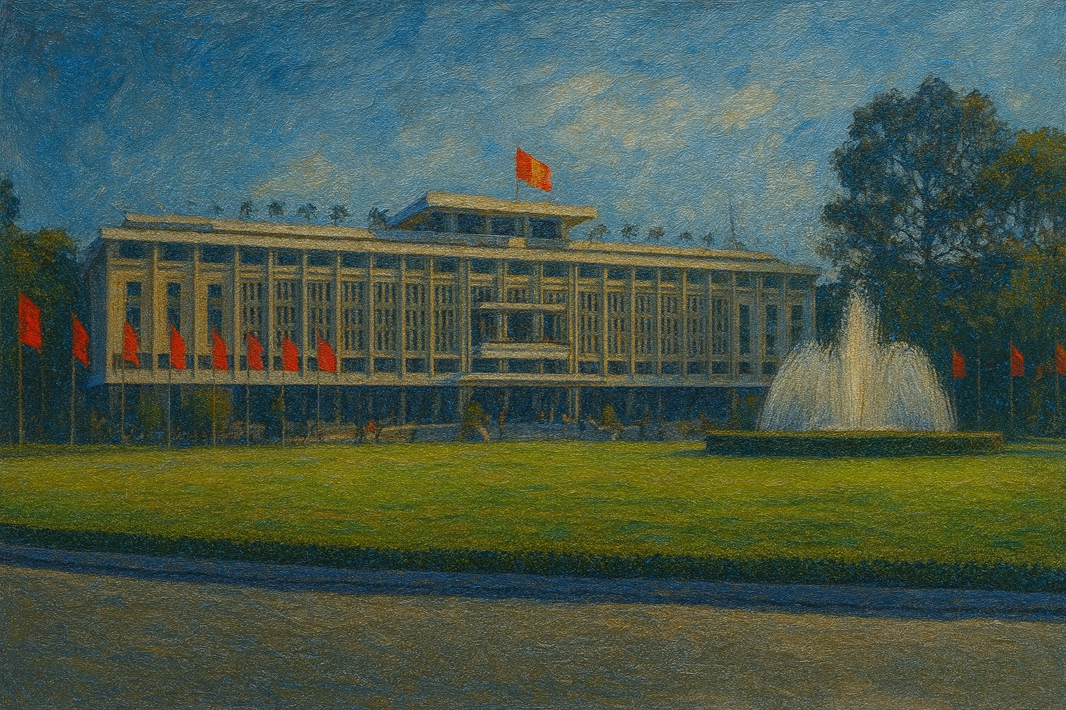
Today, visitors descending into the basement still see the gray-green T-368 racks standing silent, their heavy control panels crisp as if time stopped before 1975. Nearby are R-390 receivers, old teleprinters and paper tape; the cipher gear is gone, but the cabling remains orderly. For military-radio enthusiasts, the Reunification Palace basement offers a rare, in-person look at this Cold War behemoth: through its weighty panels and coils one can almost hear the echo of the ether—radio technology and wartime history intertwined.